
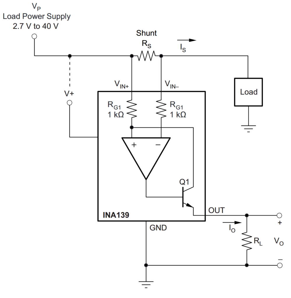
20 14 Steps with Pictures Circuit Diagram The idea is that you could build such a current sensor yourself and that's what this article is all about. The only hurdle is to measure low voltage drop. In the modules that I have dealt with so far, the shunt had a resistor of 0.1 ohms. Even with a fairly high current of, for example, an ampere, the voltage drop is just one hundred millivolts.
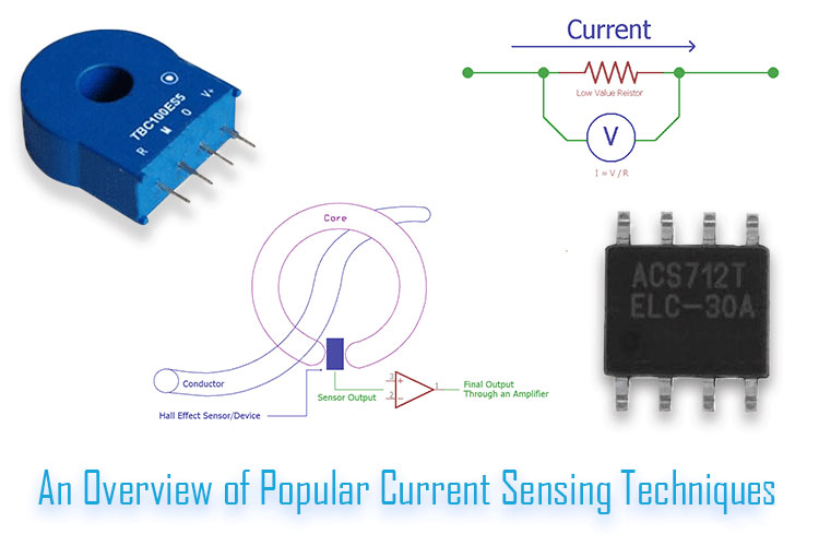
fundamentals of current sensing circuits. It introduces current sensing resistors, current sensing techniques and describes three typical high-side current sensing implementations, with their advantages and disadvan-tages. The other current sensing implementations are beyond the scope of this application note and reserved Current sensor circuits are used extensively in systems such as battery management systems in order to detect the current to monitor for overcurrent, a short circuit, and the state of charge of the battery system. so that you don't create a dangerous circuit. So how a current sensor works is that it's put in series with the circuit.
An Engineer's Guide to Current Sensing (Rev. B) Circuit Diagram
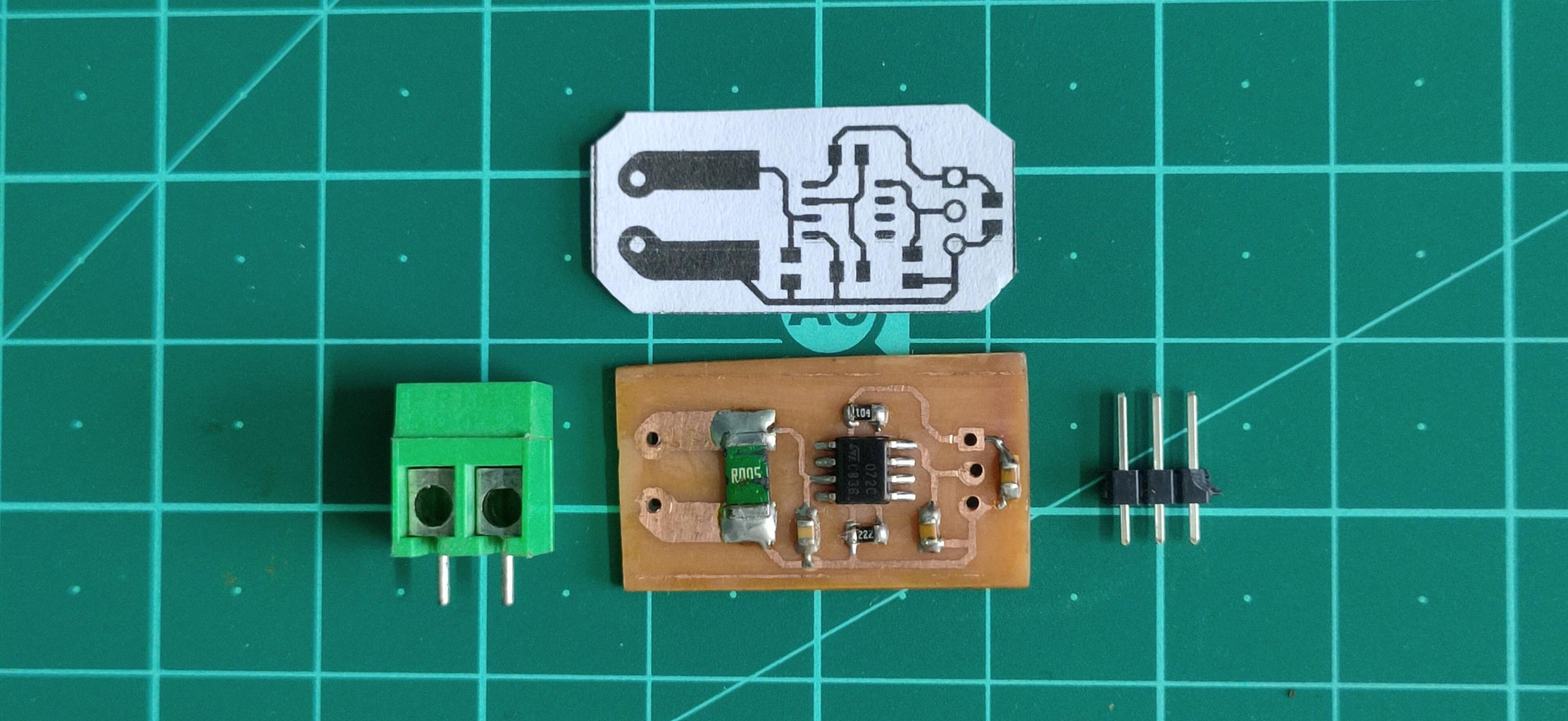
This project features a compact design and an all SMD component based circuit, making this sensor module very compact for it's range. This current sensor can easily be used for measuring currents up to 15 Amps constant and can even handle about 20 Amps peak.
Current sensing example circuits - quiz 5. Overcurrent detection is used to: a) Alert when load current has exceeded a specified threshold b) Help ensure that electronic systems operate safely c) Help a control system decide if power needs to be turned off d) All of the above 6. The INA302 and INA303 are examples of: a) A current sense comparator
PDF Low Circuit Diagram
It is unlikely that any particular circuit shown will exactly meet the requirements for a specific design, but the suggestion of many circuit techniques and devices should prove useful. allow for very wide range current sensing. In this circuit a six decade range of current pulled from the circuit input terminal is converted to an output
