Aktu Btech Sensor and Transducers Important Unit Circuit Diagram We will be using the Hall effect sensor and a magnet to find the number of times the car wheel rotated in a minute.The sensor and magnet will be placed in a such a way that at a particular point in every rotation of the wheel the sensor will detect the magnet. One of the draw backs of this code is that the first measurement of speed is The GND of the sensor is connected to the GND pin on the Arduino. The Vout or signal pin of the Hall effect sensor is connected to the Arduino's interrupt pin (digital pin 2). Furthermore, a 10K resistor is connected between the VCC and Vout pins of the Hall effect sensor. This is done to pull the output of the Hall effect sensor to 5V. I've decided to upgrade the car with RPM measurement using Hall sensor and a neodymium magnet. In the following steps I'll describe the parts needed for the setup and will provide the code. I also use the IR remote to change speed of the motor (I change the PWM signal +/-20) to check if the code and the setup is working.
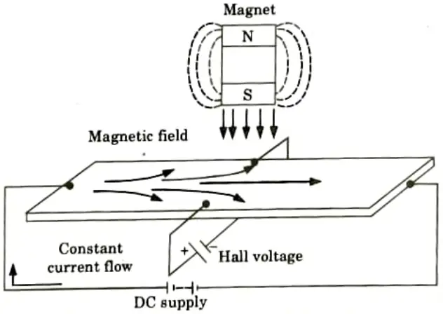
One of the popular applications of hall effect sensors is in automotive systems where they are used to detect position, measure distance and speed. They are also used in modern devices like smartphones and computers and also used in different type of switches where the presence of a magnetic field is used to either activate or deactivate a circuit. Hello, hope you are well. I have a project in electronics in which I need to measure the rotational speed of a fan using a hall effect sensor and display this speed on a 16x2 lcd. I have no problem with the display on the LCD. But I don't know how to go about it with the hall effect sensor to be able to measure the rotational speed of a fan. The optical encoder has looser positionning tolerance but requires to be completely in a box to prevent light from seeping in. The hall effect system is more tolerant to harsh environment but a bit harder to setup. With a hall sensor system, you can use a teethed wheel. You can also remove one tooth if you need to detect an absolute position too.
Arduino Speedometer Using Hall Sensor and Magnet Circuit Diagram
Hello, I am trying to measure the speed of a bicycle wheel using a hall effect sensor. I am using the code below and get the RPM which I then convert into m/s. However, I want the measurement to be more accurate. Using my code the RPM changes by 60 which is roughly 2 m/s. I want a more accurate speed measurements with not such big intervals Use the long 5-pin Wireling cable to connect the Hall-Effect Sensor to Port 0 on the Wireling TinyShield. Connect the TinyScreen+ to your computer via the micro USB cable. Step 2: Software Open your Arduino IDE and select the TinyScreen+ from Tools -> Board. Confirm that you are connected to the correct port.