
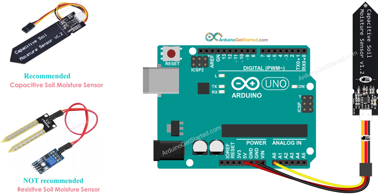
Capacitive Soil Moisture Sensor V12 Circuit Diagram upload the code which I have made into your Arduino board ; Open the serial monitor and whoola you will see the sensor reading; Now you would modify the code, you may take the variable that has the sensor value and can switch on or off any external components such as water pump and or some other thing just by making the pin high which the sensor value variable is below a certain threshold.

Assemble your soil moisture sensor circuit on a breadboard, as shown in the slideshow and described in Table 1. For advanced students, see the Help section for a circuit schematic and detailed description of how the circuit works. Click through the slideshow for step-by-step visual instructions.
Diy Soil Moisture Sensor Cheap Yet Accurate Circuit Diagram
🌱 DIY Soil Moisture Sensor Circuit | Automatic Plant Watering System 🌱In this video, I'll show you how to make a Soil Moisture Sensor Circuit to automatica
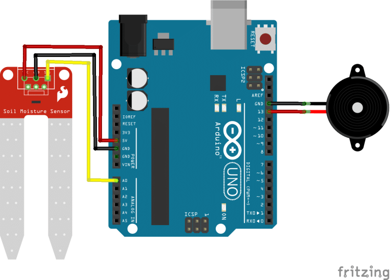
Build a simple soil moisture sensor (no programming required) that you can use for a science project! The sensor also works as a water level detector. Comple A Soil Moisture Sensor measures the water content in the soil by detecting changes in electrical resistance. Dry soil has high resistance, while moist soil has lower resistance, allowing the sensor to provide an analog or digital output representing the moisture level. Feeding the sensor with an AC or a pulsating DC may fix this problem for a little, but we prefer to make a capacitor as a soil moisture sensor. There are some advantages to a capacitor. You avoid corrosion , but capacitive measuring also gives a better reading of the moisture content of the soil in comparison with the resistance measurement.
_bb_6TRbC6Vxtj.jpg)
Simple Soil Moisture Sensor/Detector Circuit Circuit Diagram
Soil Moisture Sensor Pinout. The Soil moisture sensor a.k.a the soil humidity sensor has four pins VCC, GND, Aout, Dout.These four pins can be used to get the soil moisture data from the sensor, The pinout of the Soil Moisture Sensor are as follows:. VCC is the power supply pin of the soil moisture sensor that can be connected to 3.3V or 5V of the supply. The relay contacts switch OFF the motor pump. The pump remains OFF as long as the moisture sensor does not become dry again. The moisture sensor can be inserted deep into the soil whose moisture content needs to be sensed and controlled through the motor pump water. The pot R4 can be used to adjust the sensitivity of the moisture sensor element.