
Capacitor Selection Circuit Diagram Connecting a 1 µF capacitor from VIN to GND reduces the circuit sensitivity to the printed circuit board (PCB) layout, especially when long input traces or high source impedance are encountered. If greater than 1 µF of output capacitance is required, the input capacitor should be increased to match it. Input and Output Capacitor Properties Selection: Match the value specified in your circuit design. Use standard values (e.g., 10μF, 100nF) unless precision is critical. B. Voltage Rating. Definition: The maximum voltage a capacitor can withstand without breakdown. Rule of Thumb: Choose a rating ≥1.5× the circuit's operating voltage. For example, use a 25V capacitor for a 12V

Ceramic Capacitors: Application: Widely used for general-purpose coupling, decoupling, and filtering applications. Values: Available in a wide range of capacitance values, typically from picofarads (pF) to microfarads (µF). Example: Ceramic capacitors are commonly used in power supply circuits for smoothing and decoupling. Electrolytic Capacitors:
How to choose the right capacitor for any application Circuit Diagram
But basic doesn't mean simple. There's a rich variety of capacitor types and ways to use them, and even seasoned engineers may need some help in pairing the right capacitor with the right circuit. The engineer's complete guide to capacitors aims to provide that help. Throughout this series, we'll examine the most popular types of

This guide explains the role of capacitors on circuit boards, covering their types, functions, selection criteria, and troubleshooting techniques. It provides practical insights for engineers, designers, and hobbyists to optimize circuit performance and repair faulty components.
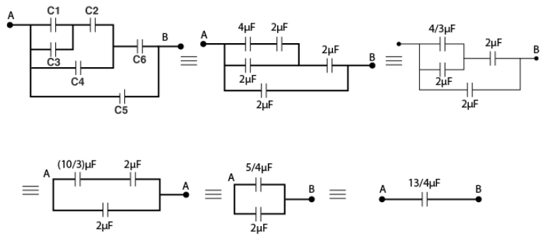
Complete List of Capacitor Selection and Formulas Circuit Diagram
Polarized capacitor; Non-polarized capacitor; The difference between a polarized capacitor and a non-polarized capacitor is that the polarized capacitor has a positive and a negative side. So it must be placed with the positive pin where the most positive voltage is. You can place the non-polarized capacitor in any way you want.
