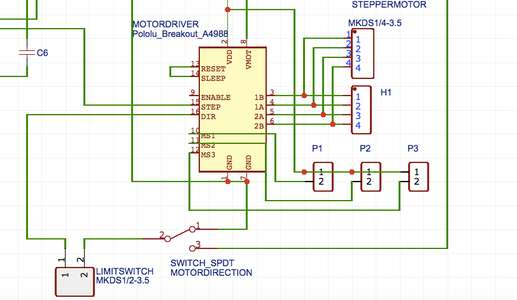
construction and control circuit Tag your friends Circuit Diagram The controller we are going to built is based around A4988 stepper motor driver.Its a relatively cheap and can easily be found on any online electronics store.Now before we get into more details have a look at the data sheet of the stepper driver. The driver needs a PWM input on the step pin to operate the motor.

This non-control is present because of the moment of inertia, For the stepper motor to work properly and non-stop we need a stepper motor controller. So here we design a simple 555 timer stepper motor controller circuit with a few easily available components, it makes the stepper motor drive continuously without any interruption or step stop. Stepper motors are available in several versions and sizes with a variety of operating voltages. The advantage of this general-purpose controller is that is can be used with a wide range of operating voltages, from approximately 5 V to 18 V. It can drive the motor with a peak voltage equal to half the supply voltage, so it can easily handle stepper motors designed for voltages between 2.5 V Note: Building a Stepper motor driver is more about selecting the proper power supply and driver, and the selection of the micro-controller is secondary. Many micro-controllers can do the simple job of rotating the motor. Still, the design considerations regarding the voltages and currents you must focus on while designing the driver.. Also, a single driver board must handle voltages and

Stepper Motor Controller Circuit Circuit Diagram
Built for the Job: The A4988 is specifically designed for bipolar stepper motors like the NEMA 17. It can handle up to 2A per coil (with proper cooling) and works with a wide voltage range of 8V to 35V, making it flexible for most hobby projects and small-scale robotics.; Microstepping Magic: Want smoother, quieter motor operation? The A4988 delivers with 5 microstepping modes (full step, half

Control stepper motors with precision! Build your own driver circuit. This guide simplifies the process with clear explanations, component lists, and step-by-step instructions. A Stepper Motor Driver is a circuit or device that provides the necessary current and voltage to a Stepper Motor so that it has a smooth operation. A Stepper Motor Get 10 PCBs for Only $5 (First Order Completely Free) https://www.pcbway.comIn this video I am going to show you how to make a stepper motor controller usin Arduino Stepper Motor Position Control Circuit Diagram and Explanation: The circuit Diagram for the arduino stepper motor control project is shown above. We have used the 28BYJ-48 Stepper motor and the ULN2003 Driver module. To energise the four coils of the stepper motor we are using the digital pins 8,9,10 and 11.