Earthquake Sensor Circuit Seismic Sensor Circuit Diagram Learn how to make a very simple wireless shock, vibration, or pressure sensing alarm that can be used for a wide range of applications, including letting you
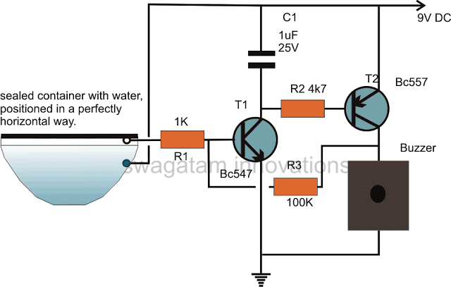
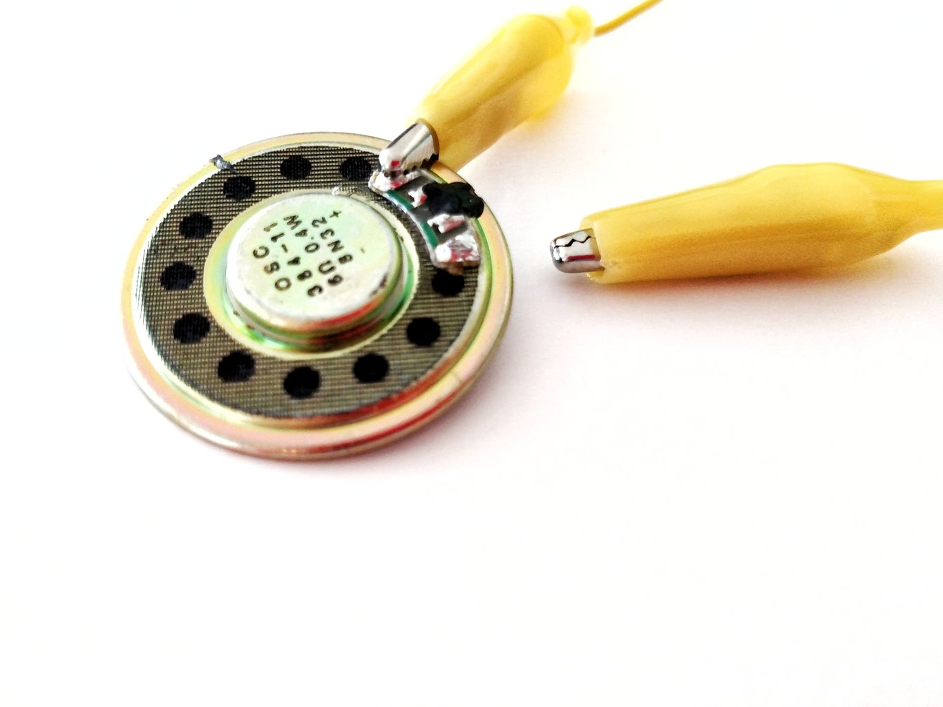
Excellent pressure sensing alarm circuit that uses a piezo wafer which has many uses!Schematic here:http://electroschematics.com/6122/pressure-sensor-alarm/C
Shock Sensor Module with Arduino Circuit Diagram
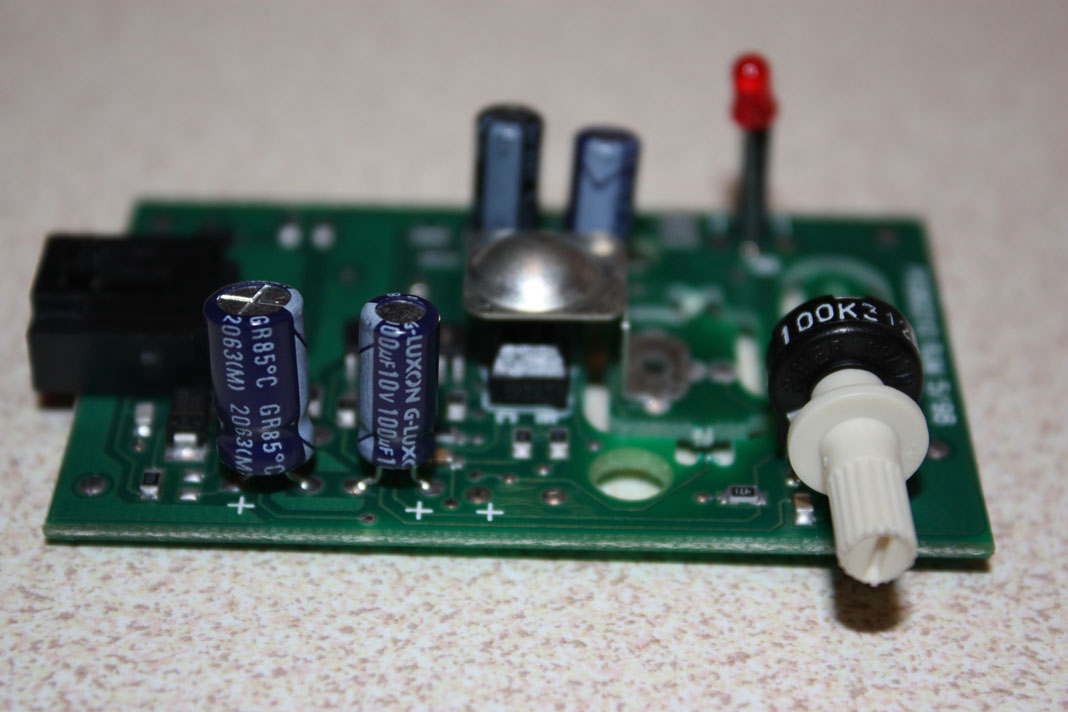
I was surprised as I though the sensor would do whatever the ultrasonic did. Perhaps the ultrasonic sensor does not power down, but somehow is simply ignored. I am unsure how a sensor in parallel on the same circuit can still set off the alarm but it does! Update The ultrasonic alarm does in fact arm even if the moonroof is left partially open. The circuit can be powered by a voltage that can exceed 12V, which is the case in a car and almost all domestic alarm systems. Construction. The printed circuit board layout and the component placement diagram of this 801S shock sensor is shown in the Figure below.

Geekcreit Shock Switch Sensor Module Circuit Alternate Shock Switch Sensor Module Circuit. If your shock sensor is configured with the 10k resistor connected between pins 1 and 2 of the module, then choose one of the following circuits. Circuit Connections to Arduino: +5V connects to the Arduino 5V pin. GND connects to the Arduino GND pin.

Simple Shock Sensor Alarm Circuit Circuit Diagram
To build a Simple Shock Sensor Alarm Circuit follow the below mentioned steps: Gather all the component as mentioned in the above circuit diagram; Connect pin 1 of IC1 LM358 to anode of diode D1 and cathode of D1 to on end of buzzer and the other end of buzzer to GND.