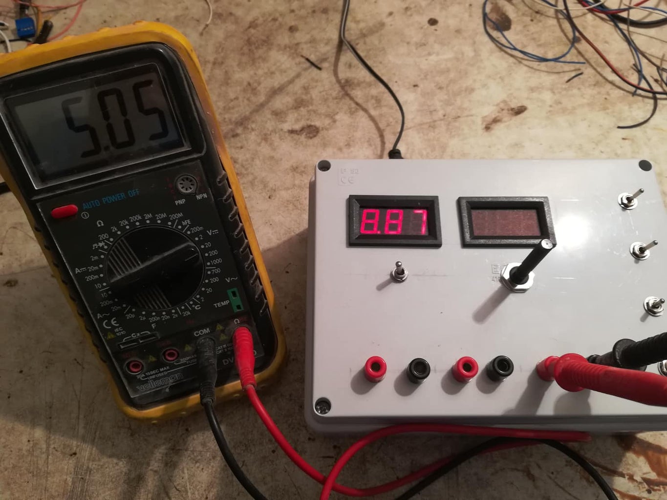
How to make digital adjustable power supply Circuit Diagram For about $5-$10 you can have your own adjustable power supply to power various electronics! If you feel comfortable with adding capacitors to the design, all you have to do is connect the capacitors in parallel with the voltage in (+) and voltage out (-) of the regulator. Make sure that the capacitor is rated for at least 25v or higher

Learn how to create a versatile 0-50 V adjustable switching power supply circuit using the LM2576 IC with this simple and hands-on tutorial designed for those with fundamental electronics understanding. The above diagram shows a simple 1.2 V to 50 V switching power supply circuit using the LM2576HV-ADJ IC, which can produce a maximum output I easily get continuously adjustable output voltage (1-30V) and current (0-6A), which is pretty enough for circuit testing and other things.I'm also using 7805 voltage regulator IC for 5V constant voltage and current. This Power Supply Has Following Features: Input Voltage 12V DC. Input Current 3A. Output Voltage (1-30V) Continuously Adjustable. The Essential Role of Adjustable Power Supplies. An adjustable power supply is a cornerstone of any electronics workbench, regardless of your experience level. It provides a variable source of power, making it useful for a wide range of tasks. From powering delicate circuits to powering motors and relays, an adjustable power supply is a must

LM317 Power Supply (My First Circuit) Circuit Diagram
Designing a simple dual power supply actually involves a just a center tap power supply and a bridge rectifier along with a couple of high value filter capacitors as shown below: However, for achieving a regulated dual power supply with the desired level of dual voltage at the output is something which normally requires a complex design using
![How to make adjustable voltage simple dc power supply [DIY] Circuit Diagram](https://i.ytimg.com/vi/EZ1E8YfTVD8/maxresdefault.jpg)
How to Connect LM317 in a Adjustable Voltage Power Supply Design. As can be seen the diagram, the assembly needs hardly any components and is in fact a child's play to get everything in place. Adjusting the pot produces a linearly varying voltage at the output that may be right from 1.25 volts to the maximum level supplied at the input of the Ic.

Designing Simple Power Supply Circuits Circuit Diagram
output power supply from a 12V source. The design uses TI's DCAP™ IC technology for the output control. This control strategy is well suited to an AVS application because of the improved transient capabilities. The www.ti.com SSZTCK3 - JUNE 2015 Submit Document Feedback Power Tips: How to Create an Adjustable Output Power Supply 1 In this project, I have designed a simple adjustable voltage DC power supply using the LM317 IC with an LM317 power supply circuit diagram. As this circuit has an inbuilt bridge rectifier so we can directly connect 220V/110V AC supply at the input. The circuit converts 230volt / 110volt AC to 0-12volt DC. Before the PCB design, I have

Choose a simple first. LM317 adjustable voltage regulator 1.2V to 10V. This is also LM317 based variable power supply and low noise, adjustable voltage output: 1.25V to 10VDC (0-12V) How can design small robot and variable power supply from 0v to 60v. Reply. ElecCircuit.com. September 7, 2017 at 11:25 pm

