Make a Digital Thermometer 5 Steps Circuit Diagram A similar precision temperature sensor is LM34 that can be used to measure temperature in Fahrenheit. It can be used to get the temperature directly in Fahrenheit. Circuit Design of Digital Thermometer. LM35 is the temperature sensor used in this project. The output of the sensor is directly proportional to the temperature but in analogue form.
This instructable guides you to build a simple digital thermometer and hygrometer that will allow you to monitor these two key environmental parameters at your workstation or in your room. It uses an Arduino Uno or its compatible board, a MAX7219-driven seven segment LED displays, and an inexpensive DHT11 sensor.

Build a Simple Digital Thermometer with Display Circuit Diagram
IntroductionA Digital Thermometer is a practical project that demonstrates how to measure and display temperature using electronic components. This project is an excellent introduction to interfacing sensors with microcontrollers and displaying data on an LCD. In this tutorial, we will build a Digital Thermometer using an Arduino, a temperature sensor (LM35), and an LCD display. This project demonstrates how to build a simple digital thermometer using a DS18B20 temperature sensor and a 16x2 LCD display with Arduino. Components Required. 1 x Arduino Board (e.g., Arduino Uno) 1 x DS18B20 temperature sensor; 1 x 16x2 LCD display (with I2C module for easy wiring) 1 x 4.7kΩ resistor (for the DS18B20) Jumper wires; Breadboard

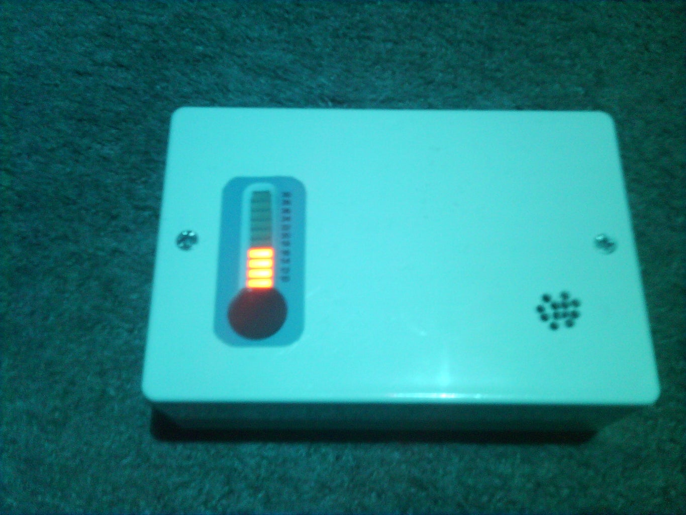
By andy70707 in Circuits Sensors. 61,564. 31. 17. Introduction: Make a Digital Thermometer. By andy70707 Follow. More by the author: In this instructable, you will learn how to make a simple digital thermometer for under £10 using a few simple components and 1 IC. Finished project should look something like this: We chose the latter, as this enables us to use our thermometer inside a fish tank, but you can pick any variant of the DS18B20 temperature sensor. Unlike other types of temperature sensors, DS18B20s provide a direct-to-digital signal to your Arduino, rather than the analog signals that come from options like LM35 temperature sensors. The DS18B20 sensor is a 3-pin electronic component (like a simple transistor) from Maxim (formerly Dallas) which uses 1-wire protocol to communicate with master device (microprocessor, microcontroller ….). Each DS18B20 device has a unique 64-bit serial code, which allows multiple DS18B20s to function on the same 1-Wire bus and controlled with
Building a Digital Thermometer with TinkerCAD and Arduino Circuit Diagram
Circuit digram for Digital Thermometer using Arduino and LM35 Temperature Sensor , is shown in the above figure. Make the connections carefully as shown in the schematic. Here 16x2 LCD unit is directly connected to arduino in 4-bit mode. Data pins of LCD namely RS, EN, D4, D5, D6, D7 are connected to arduino digital pin number 7, 6, 5, 4, 3, 2.