Most simple FM transmitter circuit diagram under Repository Learn how to make a simple FM transmitter circuit with a transistor, inductor, capacitor, and antenna. See the block diagram, working, application, and advantages of this circuit. Our detailed guides, tutorials, and circuit diagrams provide step-by-step instructions, optimization tips, and creative ideas for building and customizing FM transmitter circuits. Share your audio content with the world using our curated selection of high-quality FM transmitter circuit. A list of FM transmitter circuits with schematic diagrams for hobby and project purposes.Includes short and long range, simple and easy transmitters. Home; DIY Electronic Projects Stereo FM Transmitter using BA1404 IC - This is a stereo FM transmitter circuit using an IC from Rohmm semiconductors named BA1404 - which is a monolithic IC
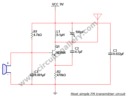
FM Transmitter Circuit Diagram and Explanation. Connect the components as shown in the Simple FM transmitter circuit below. This is how this simple FM transmitter circuit looks on breadboard . The audio output signal from the microphone is usually small, the first transistor thus performs the job of amplifying that signal to a level good enough
Fm Transmitter Circuit Diagram With Explanation
SMD FM Transmitter. Let's construct a low-power FM transmitter using surface-mount devices (SMD) that will be received with a standard FM radio. Soldering surface mounted devices is not so hard and actually is quite easy. The figure below shows the schematic of the transmitter which consists of two stages: an oscillator and an output amplifier.

Learn how to build an FM transmitter circuit using a transistor, inductor, capacitor and a microphone. See the block diagram, circuit diagram and the frequency modulation process of the FM signal. This is a simple wireless FM transmitter circuit which uses RF communication to transmit the medium or low power FM signal. Its maximum range is 2 km. Skip to content Circuit Diagram of 2 km FM Transmitter Circuit: FM Transmitter Circuit Diagram - ElectronicsHub.Org Circuit Components: Component Name Value; R1: 18K: R2: 22K: R3: 90K: R4 An FM transmitter circuit is a high frequency wireless device which is able to transmit voice signals into atmosphere so that it can be received by a. The circuit diagram for the CMOS Transmitter can be seen in the following figure. Power to the circuit is derived via B1, which is a 9 volt battery. A pair of 4011 NAND gate stages, U1c and