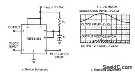
Pulse Width Modulation Schematic Diagram Circuit Diagram PWM (Pulse Width Modulation) is an essential feature of today's microcontroller because of the need to control many devices in almost every field of Electronics. 555 Timer IC is a highly convenient and versatile IC that you can use in many applications.Here we will use a 555 timer IC for generating PWM.

Simple (and Dirty) Pulse Width Modulation (PWM) With 555 Timer: Simple circuit for DC Motor speed control (fan speed control, light / LED dimming and etc) using the 555 timer.Also a good starting point for novices wanting to get their hands dirty with the 555 timer IC. Some would argue that this is not the most …
Build A Simple Pulse Width Modulation Controller / PWM Circuit Diagram
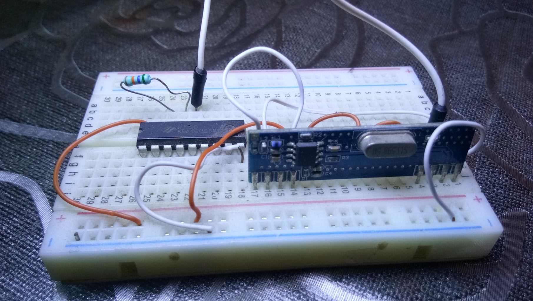
Fig. 11: Circuit Diagram of Pulse Width Modulation (PWM) The 1M ohm resistor is used to adjust the amplitude of the sine wave signal generated by the WBO. The amplitude of the sine wave should be adjusted in such a way that it matches with the amplitude of the ramp signal generated. The image of PWM circuit wired in the breadboard is given below:

PWM(Pulse Width Modulation) Remote Control Using Arduino and HT12E & HT12D: Hey! Guys How You all doing! Today I am Back With Another Cool and Very useful INSTRUCTABLE . I am pretty sure if you guys ever tried of making remote controlled vehicles like drone or robot then you must have come across the word "Remote Controller…
PWM(Pulse Width Modulation) Remote Control Using Arduino and HT12E ... Circuit Diagram
Pulse-width modulation (PWM) is a modulation technique that is used by most communication systems for encoding the amplitude of a signal right into a pulse width or duration of another signal, usually a carrier signal, for transmission.PWM is an important feature of every microcontroller due to its requirement for controlling many devices in almost every field of electronics. This video will describe how to build a simple PWM circuit and how it works. A CD4093 Nand gate logic IC will be used instead of the commonly used microcont
Make a power pulse controller for driving transfromers, motors at variable power and frequency levels. Square wave, variable frequency, variable pulse width. This can be used for many things such as DC motor speed control, lamp or LED dimming, Transformer drivers. Ignition coil circuits and other high voltage PSU's

Very Simple PWM With 555...Modulate Every Thing Circuit Diagram
How to make Pulse Width Modulation (PWM) Motor Speed Controller using NE555 & IRFZ44NRequired Components:-1) IC NE5552) 10K Resistor3) 100K Potentiometer4) 1