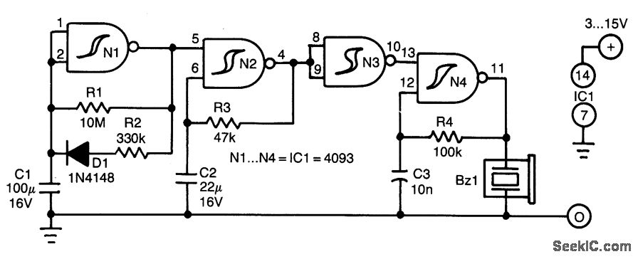
Simple Car Indicator Circuit Wiring Diagram Circuit Diagram In the above design we find that an automatic power failure indication is provided by a single transistor and a small piezo buzzer. Circuit Description. The above power failure indicator circuit design is quite identical to the 1st design using LED and capacitor. Here, instead of the LED we use a piezo buzzer.
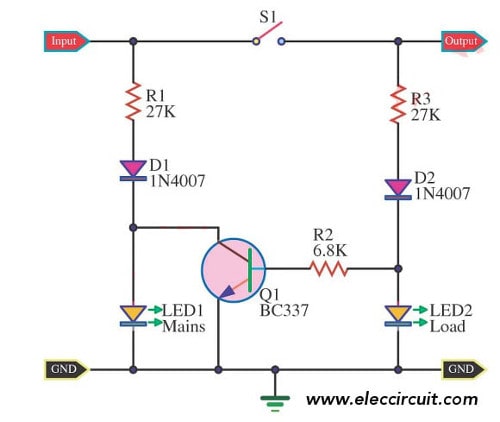
The design for the AC Line-Voltage Monitor circuit is shown in the above figure. The circuit, as previously noted, is powered by a wall transformer rated at 12 volts DC. Two quad LM324 op-amp ICs (IC1 and IC2) are the heart of the circuit, and they are powered by regulated power from a fixed DC supply that is supplied by a 5.1-volt Zener diode In this easy electronics tutorial, we'll show you how to build a **Reverse Polarity & Fuse Blown Indicator Circuit**. This simple but essential circuit helps In addition, the otherwise mandatory mains power indicator is not required with equipment that consumes less than 10 watts. As a result, you can easily forget to switch off such equipment. Here for this, we design a simple circuit with easily available components, it provides the status of the presence of the main power supply through

How to Build a Reverse Polarity & Fuse Blown Indicator Circuit Circuit Diagram
A low-battery indicator circuit is shown in the schematic diagram. This battery indicator circuit will indicate the low battery condition by flashing the LED. This circuit utilize zener diodes as a voltage reference and 741 op amp as voltage comparator to detect if the voltage falls below a preset value.

Last Updated on March 16, 2024 . Simple Battery Level Indicator Circuit designed by using IC LM3914 - dot/bar display driver from Texas Instruments. This circuit detects battery charging level and indicates the percentage of charge through 5mm LEDs. First three Red LEDs are indicates 0 to 30 percentage battery, Orange Color LEDs are indicates 40 to 60 percentage battery level and Green LEDs Building a Simple 12v Battery Full Indicator Circuit • 12v Battery Full Indicator Circuit • Learn how to easily create a 12v Battery Full Indicator Circuit u

Battery Level Indicator Circuit Circuit Diagram
How to make a simplest 12v battery full charge indicator circuit at home with simple diagram. Basic 12v car battery full charge status monitor circuit board.
Let's design a simple circuit to know the percentage of charge in a battery. I am going to take a 12V Li battery and keeping it as an example , the design the battery charge indicator circuit is explained below. Now for a typical 12V battery the voltage at various charge levels will be