
The currentlimiting circuit proposed in 5 Circuit Diagram Ohm's law states that a resistor's voltage drop is proportional to its current. A current-limiting diode circuit includes a diode in series with the load. Instead of a fixed resistance, the diode conducts when the current exceeds a threshold. Advantages and Disadvantages of Current Limiting Circuit. The use of these circuits comes with both Hello friends, I hope you all are doing great. In today's tutorial, we will have a look at Introduction to Current Regulator Diode. The current regulating diode is also known as a current limiting diode or constant current diode that used to limit the current for specific devices irrespective of variation in voltage.These diodes comprise of the N channel Junction Field Effect Transistor 3/10/2008 Steps for Analyzing Limiter Circuits 2/4 Jim Stiles The Univ. of Kansas Dept. of EECS Step 1: Assume that the limiter diode is forward biased, so replace with a CVD model, where the ideal diode is forward biased: Now, using this model, determine: 1. The output voltage v O in terms of input voltage v I. 2. The ideal diode current i i D

Current limiter circuit for Power Supply. When the amount of current required of from a power supply exceeds its maximum capacity, we need a Current Limiter circuit. (Overcurrent protection) The voltage regulator we use is made up of a zener diode and a pass-through transistor. Current Limiting Diode (CLD) The CLD or constant current diode is basically a junction FET transistor operating with its gate shorted to the source terminal, as shown in Fig. 4a. In this configuration, the JFET exhibits a unique current-limiting characteristic as V DS is increased until the FET'S voltage breakdown limit is reached. This

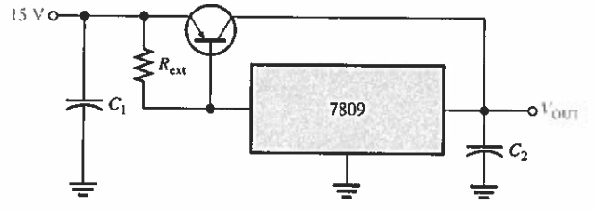
Current Limiter circuit for Power Supply using transistor & resistor ... Circuit Diagram
Instead of these exotic current limiting diodes, he could have used a current source or current sink consisting of an PNP or NPN transistor respectively, a (zener) diodes, and 2 resistors. H2 2.2 Current Limiting Diodes. Current limiting diodes, such as the zener diode, can be used to limit current in specific applications. These diodes operate by providing a fixed voltage drop, which limits the current flow. They are commonly used for low-power circuits or as protection devices in sensitive electronics. H2 2.3 Transistors Generally your current limiting circuit will require a bit of voltage "headroom" to operate in. That means you'll need an unregulated PSU of > 5 V and regulate it down to 5 V while monitoring the current. It's a while since I've read up on the old LM723 voltage regulator but they offer voltage and current limiting. These were very popular once
The diode limiter circuit comes with a resistor and diode. Based on teh circuit and biasing circuit can clip or reduce all or some part input signal. It is used to limit the output voltage to a certain value; Voltage limiter circuit. The limiter circuit can be used to limit the output voltage to increase from a certain defined value.